2.1.2. Composing of Functional Diagram.
Functional diagram is considered to be the most important one in solving designing problems. Functional diagram building-up is divided into 2 stages. The first: building-up of technological scheme with definition of a list of operations, required for fulfillment of a given technological process. And the second: choosing a design kind of tools, providing the admitted technological process variant. Both stages may be formalized.
Let's consider construction of such scheme on example of a beet-harvester. We shall use a method of morphological maps. At the first stage, main functions performed by a future machine must be specified. Here notions "function" and "element" are monosemantic. Sequence of carrying out each of interrelated functions is characterized as "interrelation".
Study of technological processes by means of morphological maps of harvester combines CK-M-3, ФĎ-3, KC-3, produced earlier, shows performing of all operations (haul pick-up, pulling, digging, haul cutting, separation, cleaning and haul-and-root-crops transporting) at one cycle is considered to be their main drawback, which complicated a design and worsened machine indexes.
Now a separated technological process is used. The first machine performs haul cutting and harvesting, and the second one does all other operations. It is no doubt, that comparing with the first machine, the second one is more complex, that's why it is this machine we shall build a functional diagram for.
Analysis shows four main functions to be specified in such machine: d'ggtng, separation, cleaning and transporting. These functions can be performed consecutively or in a consecutive-parallel manner. Suppose, that con-ecutive function performing is admitted. Number of a possible variant realization of second machine functional diagrams equal to number of rearrangements of 4 elements. As function "digging" is performed first, then diagram variants number diminishes to six (tables 2.1.).
Then, evaluation criteria, for example economical, are adopted, and the most appropriate variant is chosen. So, designers from GDR decided on the fifth variant for their machine KC-6.
At the second stage kinds of tools for performing main functions are defined. For this purpose morphological map given in the table 1.4 is used.
Table 2.1 Possible variants of beet harvester functional
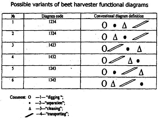
For realization of "digging" function designers of KC-6 used digging-up wheels, for separation-auger-cleaner; for cleaning - clod-conveyors , for transporting chain-and-slat and chain-web conveyors /5/.
Building a functional diagram it is necessary to pay special attention to the places of transmitting of material. In order to prevent blockage in such places it is possible to repeat function "transporting" and to put agitators promoting better moving of material.
In a considered combine KC-6 a beater was set between diggers and auger-cleaners; longitudinal slanting cage-wheel elevator was set between a clod conveyor and a chain and slat conveyor; these operations permitted designers to achieve high quality of a technological process.
As it is seen from above example, functional diagram composing is based on revelation of all alternative variants and choosing the most appropriate of them on the basis of admitted criteria.
In order to simplify these procedures, the method based on so-called usability tables was developed. It represents morphological maps, including construction signs and evaluation criteria of its possible variants.
The tables are built in the following way. As every parameter xl x2,... xn can take set discrete values in the form of
x=(xl,x2,...,xn),
then every set of parameters variants corresponds to a set of decisions
Y=(Yl,Y2,...,Ym).
If the columns are given values of parameter grouped according to their names and lines are given some solution from a solution set, corresponding to a set of parameters values in a line, then the usability table will be received. "One" in a table square means that a parameter takes a corresponding value; as usual "zero" is not written and empty space in a table means impossibility of a given parameter realization. Thus a one-to-one correspondence between parameter value set and solution is described in every table square (fig.2.1.)
═ÓšÓń ╬ŃŰÓÔŰňÝŔň ┬´ňňń