2. 5. 2. Arrangement technique.
Inversion, function coincidence, reduction of links number In mechanism, rational choice of power diagram and choice of rational parameters of machine parts are the most wide-spread procedures of arrangement technique.
Plot of inversions consists of chaining of functions, shapes and position of details, assembly units and sets. In units it is sometimes possible to change roles of details, for example, to make a driving detail a driven one, directing - directed one, covering - covered , stationary- mobile. Sometimes it is expedient to invert shapes of details, for example, to replace an external cone by an inner one. In the other cases it is expedient to transfer constructive elements from one detail to another, for example: key - to hub,, a lever pin - to rusher.
Each time construction acquires new properties. It is a designer's work - to consider advantages and drawbacks of initial and inverted variants, taking :nto account such factors as strength, adaptability to manufacture and convenience to operation and to choose the best one. An experienced designer can use inversion method as an inalienable tool of brain, which consid-erably facilitates process of decision search, as the result of which a new rational design is born.
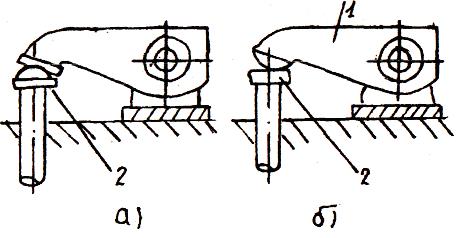
Fig2.11. Application of inversion method in a camshaft design!
(IM-raditiona! diagram; b- inversion diagram;
1- rocker pin; 2- pusher plate)
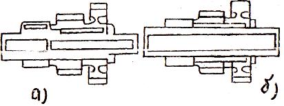
Fig 2.12.Application of function coincidence
technique in gear-biock constructions;
a,b - old and new constructions respectively
Coincidence of construction functions is^used when reduction of sizes and mass of construction is required. For example, in gear-block (fig. 2. 12.) fitted gear-wheels are mounted on continuation of a gear-shaft tooth, and due to this operation strength of a shaft grows, diameter of right neck increases and machining simplifies.
Reduction of the number of links promotes considerable reduction of a unit weight. For example, in a cam drive construction (fig.2.13,b) cam acts upon a rocker by means of a pusher.
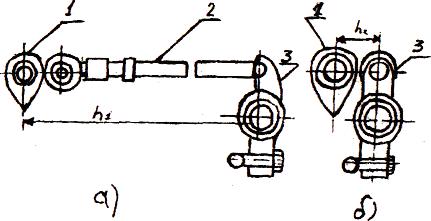
Fig 2.13. Reduction of number of links in cam
drive construction; a,b - old and new constructions
respectively; 1-eiam; 2- pusher; 3- rocker.
Íŕçŕä Îăëŕâëĺíčĺ Âďĺđĺä