2.1.4.Building of Schematic Diagrams
In designing schematic diagram serves a basis for elaborating of sr designing documents. Building it the results received during study of unctional and kinematic diagrams are used. Machine is embodied in such a diagram with regard to reference elements, working place of operator, etc.
Schematic diagram is to permit solving of such designing problems, as adaptability to manufacture, technical operation and repair, ergonomics, environmental protection, transportability and all others, reflected in RFP.
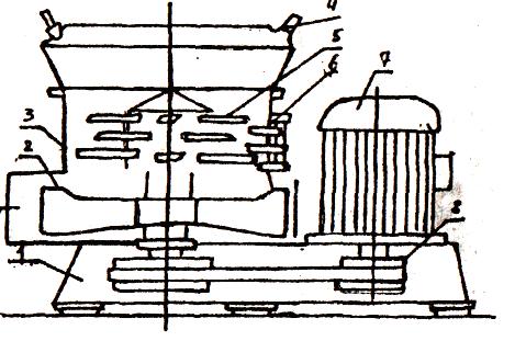
Fig 2.3. Schematic diagram of fodder shredder mixer of ИСК-3 mark:
1-frame;
2-spinner;
3-concave;
4-injector;
5-rotor;
6-piles of counter-cuts;
7- motor;
8- rotor drive
Schematic diagram is carried out in the form of diagrammatic section Outline is performed in accordance with each element and device design. Elements, making up functional groups or devices, are assumed to be marked on a diagram by fast-and-dot lines, the name of a group and the name and code of a device being indicated.
Elements making up a device and having independent schematic diagrams are marked at the schematic diagram by a continuous line, which is two times thicker than connective lines.
Various technical data are put in the diagrams. Such information is located either near graphic symbols (to the right of or above them on possibility) or in the free field. Nominal values of parameters are put near graphic symbols of elements and devices, and diagrams, tables, texts, instructions -in - free field of a diagram.
On the basis of schematic diagram general view of machine with longitudinal sections is carried out. It allows to get all necessary information about design of machine, its assembly units and elements.
Schematic diagram and general view of fodder-shredder of ИСК-3 type, carried out on the basis of above methods are shown at fig.2.3 and 2.4.
Назад Оглавление Вперед